| ⓘ Layers |
| All elements in the panel are associated layers. The layer is described as an integer, where small values represent the background and high numbers the foreground. When placing elements, you should make sure that no overlapping elements share the same layer number. The background image of the panel is always associated layer number 0, so elements on top of it should start with layer number 1 or higher. If you want to place elements behind the panel background image, you can likewise use negative numbers to represent these layers. |
| ⓘ Daytime and nighttime images |
| For all elements that take a texture, you can specify distinct daytime and nighttime textures. Depending on the lighting conditions and additional route instructions, openBVE will display any intermediate blend between the daytime and nighttime textures. If no nighttime textures are used, the daytime images will be darkened to simulate corresponding nighttime images. |
| ⓘ Overlay and Lighting |
| The cab is rendered as an overlay. This means that the cab will always appear in front of scenery objects. This is intentional, because this way, rain, walls and other obstructing objects cannot be accidentally rendered inside the cab. Furthermore, lighting in the cab is different than in the scenery. While the ambient brightness is reflected in the cab, the ambient color is not, and the cab always appears as if reflecting white light. |
| [NameOfTheSection] |
| NameOfTheKey = Value |
| [This] |
| Resolution = Value |
| Value: A floating-point number representing the width measured on the panel background image that corresponds to the width of the screen for the default camera position, alignment and zoom. |
| Left = Value |
| Value: A floating-point representing which x-coordinate in the panel background corresponds to the farthest point to which can be scrolled left. The point is not required to lie within the bounds of the background image. |
| Right = Value |
| Value: A floating-point representing which x-coordinate in the panel background corresponds to the farthest point to which can be scrolled right. The point is not required to lie within the bounds of the background image. |
| Top = Value |
| Value: A floating-point representing which y-coordinate in the panel background corresponds to the farthest point to which can be scrolled up. The point is not required to lie within the bounds of the background image. |
| Bottom = Value |
| Value: A floating-point representing which y-coordinate in the panel background corresponds to the farthest point to which can be scrolled down. The point is not required to lie within the bounds of the background image. |
| DaytimeImage = FileName |
| FileName: The image file to use as the daytime version of the panel background image, relative to the train folder. If not specified, no background image will be shown. |
| NighttimeImage = FileName |
| FileName: The image file to use as the nighttime version of the panel background image, relative to the train folder. If specified, the daytime version must also be specified. Otherwise, no nighttime version will be available. |
| TransparentColor = HexColor |
| HexColor: A hexcolor representing the exact color in both the DaytimeImage and NighttimeImage files which corresponds to a transparent pixel. The default value is #0000FF. |
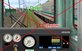
| Center = X, Y |
|
X: A floating-point number representing the x-coordinate of the panel background image that corresponds to the center of the screen. Y: A floating-point number representing the y-coordinate of the panel background image that corresponds to the center of the screen. |
| Origin = X, Y |
|
X: A floating-point number representing the x-coordinate of the panel background image that corresponds to the vanishing point. Y: A floating-point number representing the y-coordinate of the panel background image that corresponds to the vanishing point. |
| ⓘ When camera restriction affects the default camera setup |
| Camera restriction is the built-in functionality to limit the camera view inside cabs created by the panel2.cfg to the rectangle as specified via Left, Right, Top and Bottom. If your setup of Center and Resolution would force the camera to show parts that are outside of that specified region even with the default camera settings, the camera position will be altered to guarantee that the view stays inside the cab region. In order to verify that your Center and Origin setup is unaffected by this, disable camera restriction by hitting the CAMERA_RESTRICTION key (default: CTRL+R) and then reset the camera by hitting the CAMERA_RESET key (default: num 5). The Center and Origin values will now be exactly as scripted, thereby revealing possible problems in the relations of Resolution, Left, Right, Top, Bottom, Center and Origin. |
| [PilotLamp] |
| Subject = Subject |
| Subject: One of the available subjects. The default subject is true. |
| Location = Left, Top |
|
Left: A floating-point number representing the x-coordinate at which the left of the image is inserted. The default value is 0. Top: A floating-point number representing the y-coordinate at which the top of the image is inserted. The default value is 0. |
| DaytimeImage = FileName |
| FileName: The image file to use as the daytime version of the indicator image, relative to the train folder. Is required to be specified. |
| NighttimeImage = FileName |
| FileName: The image file to use as the nighttime version of the indicator image, relative to the train folder. If not specified, no nighttime version will be available. |
| TransparentColor = HexColor |
| HexColor: A hexcolor representing the exact color in both the DaytimeImage and NighttimeImage files which corresponds to a transparent pixel. The default value is #0000FF. |
| Layer = LayerIndex |
| LayerIndex: An integer which uniquely defines this element among overlapping elements. Lower numbers represent the background and higher numbers the foreground. Elements may use the same LayerIndex as long as they do not overlap. The default value is 0. |
| [Needle] |
| Subject = Subject |
| Subject: One of the available subjects. The default subject is true. |
| Location = CenterX, CenterY |
|
CenterX: A floating-point number representing the x-coordinate of the center of rotation in terms of the background image. The default value is 0. CenterY: A floating-point number representing the y-coordinate of the center of rotation in terms of the background image. The default value is 0. |
| Radius = ValueInPixels |
| ValueInPixels: A non-zero floating-point number that redefines the radius of the element in pixels relative to the background image. The default value is Y from the Origin key-value pair. |
| DaytimeImage = FileName |
| FileName: The image file to use as the daytime version of the needle image, relative to the train folder. Is required to be specified. |
| NighttimeImage = FileName |
| FileName: The image file to use as the nighttime version of the needle image, relative to the train folder. If not specified, no nighttime version will be available. |
| Color = HexColor |
| HexColor: A hexcolor representing the color by which the images are multiplied with. The default value is #FFFFFF. |
| TransparentColor = HexColor |
| HexColor: A hexcolor representing the exact color in both the DaytimeImage and NighttimeImage files which corresponds to a transparent pixel. The default value is #0000FF. |
| Origin = X, Y |
|
X: A floating-point number representing the x-coordinate that corresponds to the image's center of rotation. The default value is half the image width. Y: A floating-point number representing the y-coordinate that corresponds to the image's center of rotation. The default value is half the image height. |
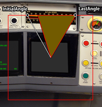
| InitialAngle = ValueInDegrees |
| ValueInDegrees: A floating-point number representing the angle in degrees that corresponds to the Minimum value. The angle is measured clock-wise from the 12 o'clock position. The default value is -120. |
| LastAngle = ValueInDegrees |
| ValueInDegrees: A floating-point number representing the angle in degrees that corresponds to the Maximum value. The angle is measured clock-wise from the 12 o'clock position. The default value is 120. |
| Minimum = Value |
| Value: A floating-point value corresponding to the value returned by the Subject in use that should be linked to the InitialAngle. The default value is 0. |
| Maximum = Value |
| Value: A floating-point value corresponding to the value returned by the Subject in use that should be linked to the LastAngle. The default value is 1000. |
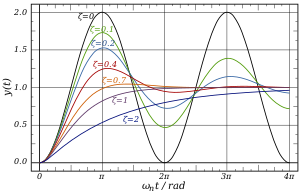
| NaturalFreq = Value |
| Value: A non-negative floating-point number representing the natural frequency of an assumed undamped oscillatory system. If not specified, damping will not be performed. |
| DampingRatio = Value |
| Value: A non-negative floating-point number representing the damping ratio. If not specified, damping will not be performed. |
| Layer = LayerIndex |
| LayerIndex: An integer which uniquely defines this element among overlapping elements. Lower numbers represent the background and higher numbers the foreground. Elements may use the same LayerIndex as long as they do not overlap. The default value is 0. |
| [DigitalNumber] |
| Subject = Subject |
| Subject: One of the available subjects. The default subject is true. |
| Location = Left, Top |
|
Left: A floating-point number representing the x-coordinate at which the left of the image is inserted. The default value is 0. Top: A floating-point number representing the y-coordinate at which the top of the image is inserted. The default value is 0. |
| DaytimeImage = FileName |
| FileName: The image file to use as the daytime version of the DigitalNumber image, relative to the train folder. Is required to be specified. |
| NighttimeImage = FileName |
| FileName: The image file to use as the nighttime version of the DigitalNumber image, relative to the train folder. If not specified, no nighttime version will be available. |
| TransparentColor = HexColor |
| HexColor: A hexcolor representing the exact color in both the DaytimeImage and NighttimeImage files which corresponds to a transparent pixel. The default value is #0000FF. |
| Interval = Height |
| Height: The height of a single state in the images in pixels. Is required to be specified. |
| Layer = LayerIndex |
| LayerIndex: An integer which uniquely defines this element among overlapping elements. Lower numbers represent the background and higher numbers the foreground. Elements may use the same LayerIndex as long as they do not overlap. The default value is 0. |
| [DigitalGauge] |
| Subject = Subject |
| Subject: One of the available subjects. The default subject is true. |
| Location = CenterX, CenterY |
|
CenterX: A floating-point number representing the x-coordinate at which the left of the image is inserted. The default value is 0. CenterY: A floating-point number representing the y-coordinate at which the top of the image is inserted. The default value is 0. |
| Radius = ValueInPixels |
| ValueInPixels: A non-zero floating-point number representing half the edge length of the solid-color square in pixels. Is required to be specified. |
| Color = HexColor |
| HexColor: A hexcolor representing the color of the solid-color square. The default value is #FFFFFF. |
| InitialAngle = ValueInDegrees |
| ValueInDegrees: A floating-point number representing the angle in degrees that corresponds to the Minimum value. The angle is measured clock-wise from the 12 o'clock position. The default value is -120. |
| ⚠ | The absolute difference between InitialAngle and LastAngle may not exceed 360 degrees. |
| LastAngle = ValueInDegrees |
| ValueInDegrees: A floating-point number representing the angle in degrees that corresponds to the Maximum value. The angle is measured clock-wise from the 12 o'clock position. The default value is 120. |
| ⚠ | The absolute difference between InitialAngle and LastAngle may not exceed 360 degrees. |
| Minimum = Value |
| Value: A floating-point value corresponding to the value returned by the Subject in use that should be linked to the InitialAngle. The default value is 0. |
| Maximum = Value |
| Value: A floating-point value corresponding to the value returned by the Subject in use that should be linked to the LastAngle. The default value is 1000. |
| Step = Value |
| Value: A floating-point value representing the step in which values on the solid-color square can increase. The value to be displayed via the solid-color square will be rounded down to the next integer multiple of Value. If Value is negative, values will be rounded up to the absolute value of Value instead. If Value is 0, increases will be smooth. The default value is 0. |
| Layer = LayerIndex |
| LayerIndex: An integer which uniquely defines this element among overlapping elements. Lower numbers represent the background and higher numbers the foreground. Elements may use the same LayerIndex as long as they do not overlap. The default value is 0. |
| [Timetable] |
| Location = Left, Top |
|
Left: A floating-point number representing the x-coordinate at which the left of the image is inserted. The default value is 0. Top: A floating-point number representing the y-coordinate at which the top of the image is inserted. The default value is 0. |
| Width = ValueInPixels |
| ValueInPixels: A positive floating-point number representing the width of the timetable measured in terms of the background image. Is required to be specified. |
| Height = ValueInPixels |
| ValueInPixels: A positive floating-point number representing the height of the timetable measured in terms of the background image. Is required to be specified. |
| TransparentColor = HexColor |
| HexColor: A hexcolor representing the exact color in both the daytime and nighttime versions of the timetable which corresponds to a transparent pixel. The default value is #0000FF. |
| Layer = LayerIndex |
| LayerIndex: An integer which uniquely defines this element among overlapping elements. Lower numbers represent the background and higher numbers the foreground. Elements may use the same LayerIndex as long as they do not overlap. The default value is 0. |
| Base subject | Description |
|---|---|
| acc | Returns the (signed) acceleration of the train in meters per second squared (m/s²). |
| atc | Equivalent to ats271. |
| atsi | Returns the state of the ith plugin variable, depending on the plugin used. This is the same as pluginState[i] in animated objects. For the built-in safety systems ATS and ATC, see below. |
| bc | Returns the pressure of the brake cylinder in kPa (1000 Pa). |
| bp | Returns the pressure of the brake pipe in kPa (1000 Pa). |
| brake | Returns the currently selected brake notch. For trains with automatic air brakes, 0 represents RELEASE, 1 represents LAP, 2 represents SERVICE and 3 represents the emergency brake. For trains without a hold brake device, 0 represents released brakes, i represents brake notch i and n+1 represents the emergency brake, where n is the number of brake notches the train has. For trains with a hold brake device, 0 represents released brakes, 1 represents the hold brake, i+1 represents brake notch i, and n+2 represents the emergency brakes, where n is the number of brake notches the train has. |
| csc | Returns 1 if the const speed system is currently active and 0 otherwise. |
| door | Returns a value between 0 (open doors) and 1 (closed doors). |
| doorli | Returns a value between 0 (open) and 1 (closed) for the left doors of car i, or 2 if the car does not exist. Car index 0 represents the first car in the train, and n-1 the last car, where n is the number of cars in the train. |
| doorri | Returns a value between 0 (open) and 1 (closed) for the right doors of car i, or 2 if the car does not exist. Car index 0 represents the first car in the train, and n-1 the last car, where n is the number of cars in the train. |
| er | Returns the pressure of the equalizing reservoir in kPa (1000 Pa). |
| hour | Returns the integer part of the current hour. |
| kmph | Returns the absolute speed of the train in kilometers per hour (km/h). |
| min | Returns the integer part of the current minute. |
| motor | Returns the acceleration which the motor of the first motor car currently generates in m/s². |
| mph | Returns the absolute speed of the train in international miles per hour (mph). |
| mr | Returns the pressure of the main reservoir in kPa (1000 Pa). |
| ms | Returns the absolute speed of the train in meters per second (m/s). |
| power | Returns the currently selected power notch. This is an integer between 0 and n, where n is the number of power notches the train has. |
| rev | Returns the currently selected reverser position. 0 represents backward, 1 represents neutral and 2 represents forward. |
| sap | Returns the pressure of the straight air pipe in kPa (1000 Pa). |
| sec | Returns the integer part of the current second. |
| true | Always returns 1. This is useful for the PilotLamp element in order to always show the associated bitmap. |
| i | English | 日本語 | Return values | ats271 | Meaning | |
|---|---|---|---|---|---|---|
| 256 | ATS | ATS | 0 (unlit) or 1 (lit) | 0 | ATC not available | |
| 257 | ATS RUN | ATS 作動 | 0 (unlit), 1 (lit) or 2 (flashing) | 1 | 0 km/h | |
| 258 | ATS RUN | ATS 作動 | 0 (unlit / non-flashing), 1 (lit / flashing) | 2 | 15 km/h | |
| 259 | P POWER | P 電源 | 0 (unlit) or 1 (lit) | 3 | 25 km/h | |
| 260 | PTN APPROACH | パターン接近 | 0 (unlit) or 1 (lit) | 4 | 45 km/h | |
| 261 | BRAKE RELEASE | ブレーキ開放 | 0 (unlit) or 1 (lit) | 5 | 55 km/h | |
| 262 | BRAKE APPLY | ブレーキ動作 | 0 (unlit) or 1 (lit) | 6 | 65 km/h | |
| 263 | ATS P | ATS-P | 0 (unlit) or 1 (lit) | 7 | 75 km/h | |
| 264 | FAILURE | 故障 | 0 (unlit) or 1 (lit) | 8 | 90 km/h | |
| 265 | ATC | ATC | 0 (unlit) or 1 (lit) | 9 | 100 km/h | |
| 266 | ATC POWER | ATC 電源 | 0 (unlit) or 1 (lit) | 10 | 110 km/h | |
| 267 | ATC SRV | ATC 常用 | 0 (unlit) or 1 (lit) | 11 | 120 km/h | |
| 268 | ATC EMG | ATC 非常 | 0 (unlit) or 1 (lit) | 12 | ATS is active | |
| 269 | CONST SPEED | 定速 | 0 (unlit) or 1 (lit) | |||
| 270 | EB | EB | 0 (unlit) or 1 (lit) | |||
| 271 | ATC speed indicator | 0 - 12, see table on the right |
| Subject suffix | Description |
|---|---|
| di | With d0 for the ones, d1 for the tens, d2 for the hundreds, etc., this suffix returns a value between 0 and 9 corresponding to the respective digit of the underlying subject, but only if the value of the subject is less than 10 for d1, less than 100 for d2, etc., otherwise this suffix returns 10. |